Threat 2: Chromium Oxide Scale (Heat Tint)
When stainless steel is heated above 800°F in the presence of oxygen, chromium oxide forms. This scale is blue, purple, or grey. It flakes off easily and becomes a permanent particle generator inside the gas line.
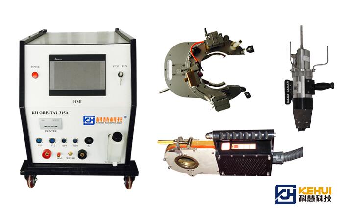
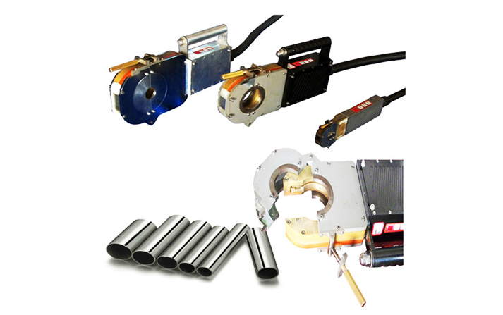
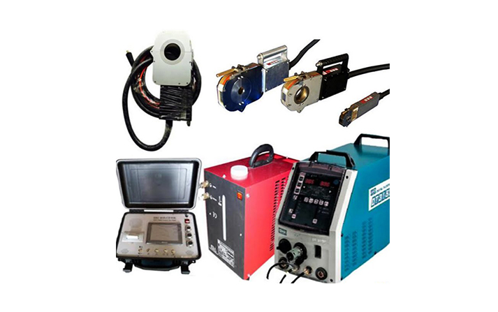
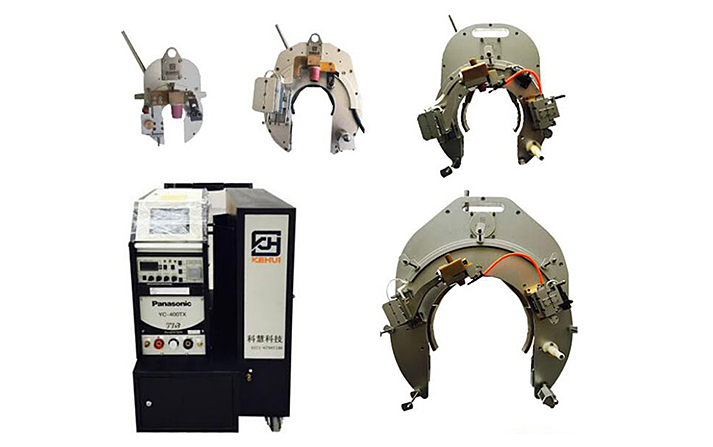
Manual welding almost always produces some oxide because the welder’s torch angle and purge flow vary. An orbital welding system eliminates this variation. The orbital tube welding machine seals the weld zone inside a gas‑tight chamber. The orbital welding procedures specify:
-
Pre‑purge until oxygen levels are below 50 ppm.
-
Post‑purge to cool the weld in an inert atmosphere.
-
Heat input limits that prevent over‑heating.
The result is a silver or light‑straw root – no oxide scale, no particle source. A properly qualified orbital welding system can achieve this on 100% of welds.
Threat 3: Tungsten Inclusions (Metal Fragments)
Manual TIG welders occasionally let the tungsten electrode touch the weld pool. The tip melts and breaks off, leaving a hard tungsten fragment embedded in the weld. These fragments are extremely dense and can break loose later, damaging valves and instruments downstream.
An orbital tube welding machine never allows the tungsten to touch the work. The orbital welding system fixes the electrode at a precise distance. The arc length is maintained automatically. Even if the operator makes a mistake during setup, the orbital welding procedures include a tungsten tip check before every weld – and a mandatory change schedule based on number of welds, not visual appearance.
We’ve seen fabs eliminate tungsten inclusions entirely after switching to an orbital welding system with disciplined orbital welding procedures.
How to Implement These Procedures in Your Fab
Switching from manual to orbital welding isn’t just about buying an orbital tube welding machine. You need to qualify orbital welding procedures on your specific tube size, wall thickness, and gas blend. You need to train operators to follow the procedure exactly – no shortcuts.
That’s where we come in. We’ve been building orbital welding system equipment since 1994. We’ve supplied closed‑head orbital tube welding machine systems to semiconductor fabs in over fifty countries. And we include engineer‑led training with every system – on your tube, in your cleanroom environment.
Our orbital welding procedures are developed jointly with your quality team. They cover purge oxygen limits, heat input windows, tungsten change intervals, and data logging requirements. The orbital welding system records every parameter, giving you full traceability for every weld.
The Bottom Line
Particle contamination in semiconductor gas lines comes from three main sources: spatter, oxide scale, and tungsten inclusions. Manual welding cannot reliably eliminate any of them. A closed‑head orbital tube welding machine, running qualified orbital welding procedures as part of an integrated orbital welding system, eliminates all three.
That’s why every major semiconductor fab today specifies orbital welding for their critical gas distribution systems. Not because it’s cheaper – it isn’t. Because the cost of a single particle‑killed wafer is far higher than the cost of doing the job right.
We’ve been helping fabs do it right for over three decades. If you’re responsible for gas line installation or maintenance, call us. We’ll show you how our orbital welding system and orbital tube welding machine – with proven orbital welding procedures – can protect your wafers from the particles you never see coming.