Stock Code: 831045
Industrial Automation & Intelligence Solutions
SUMMERY: Automating a circumferential weld on a large-diameter pipe requires more than attaching a welding torch to a motorized carriage. The system must follow the pipe circumference accurately, maintain stable travel speed, control weld bead fo...
Automating a circumferential weld on a large-diameter pipe requires more than attaching a welding torch to a motorized carriage. The system must follow the pipe circumference accurately, maintain stable travel speed, control weld bead formation, and accommodate the joint geometry and welding procedure.
For pipe fabrication shops, pipeline contractors, and pressure vessel manufacturers, the main options include orbital welding heads, track-guided welding carriages, and magnetic welding tractors. A Magnatech orbital welder, for example, can be relevant to mechanized multi-pass pipe welding, while a magnetic welding tractor may offer a practical alternative for suitable steel workpieces and field applications.
The best solution depends on pipe diameter, wall thickness, material, welding process, and whether the pipe remains stationary during welding. Understanding these factors helps manufacturers select the right equipment for reliable large diameter pipe circumferential welding.
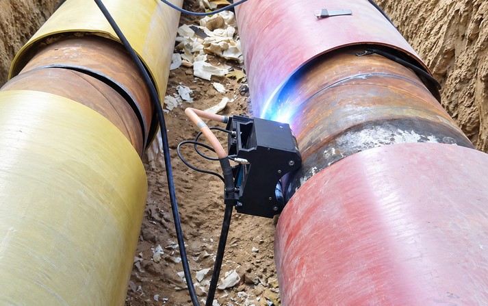
A circumferential weld, also called a pipe girth weld, joins two pipe sections around their circumference. Unlike a short straight seam, the welding position changes continuously as the torch moves around the pipe.
In real fabrication workshops, several problems can affect productivity and weld consistency:
This is where circumferential weld automation becomes valuable. Mechanized travel allows the operator to control movement and selected welding parameters more consistently across repeated joints.
However, automation does not eliminate the need for correct bevel preparation, root-gap control, tack welding, and inspection. These remain essential to achieving the required weld quality.
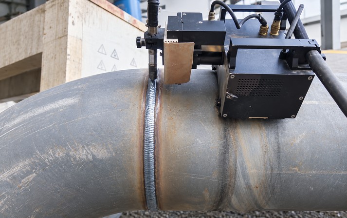
Not every automatic welding system works in the same way. Three equipment categories deserve consideration.
A Magnatech orbital welder can be suitable for applications requiring controlled torch movement and mechanized pipe welding.
For larger pipes and heavy-wall applications, the Magnatech Pipeliner II 609 is designed for multi-pass GMAW/FCAW welding. Its published specifications cover pipe diameters from approximately 168 mm (6.625 inches) and larger, with interchangeable guide rings and optional Flx-Track equipment for welding on flat and curved surfaces. The system includes functions such as wire feeding, torch movement, and electronic oscillation. Source: Magnatech Pipeliner II specifications
A Magnatech orbital welder should therefore be evaluated according to the actual application rather than the brand name alone.
Before selecting a system, check the welding process, joint preparation, pipe diameter, wall thickness, number of passes, and required production rate.
A circumferential welding carriage travels along a track or guide ring installed around the pipe.
The track establishes the travel path, while the carriage moves the welding torch around the joint. Depending on the design, the system may provide adjustable travel speed, torch positioning, and oscillation.
This approach is useful when:
For some large-pipe applications, a dedicated ring or flexible track is more practical than rotating a heavy pipe assembly.
A magnetic welding tractor moves across a suitable ferromagnetic surface using magnetic wheels or another magnetic attachment system.
Depending on its design, it may travel directly on a steel workpiece or operate with a magnetic track. The distinction matters: a trackless magnetic tractor and a carriage mounted on a magnetic flexible track are not the same configuration.
A magnetic welding tractor can be attractive for large steel structures, tank fabrication, and certain pipe-welding applications where quick positioning is important.
For circumferential welding, verify that the carriage can maintain stable traction and follow the required path around the pipe. Magnetic adhesion alone does not guarantee accurate torch tracking.
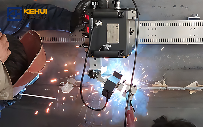
A reliable setup begins before the welding arc is switched on.
Confirm the pipe diameter, wall thickness, material, bevel angle, root gap, and alignment. Tack welds should hold the joint in position without obstructing the intended welding path.
For thick-wall pipe, the welding procedure should define the root pass and subsequent fill and cap passes.
For a track-guided circumferential welding carriage, install the guide ring or flexible track around the pipe and check alignment with the joint.
For a magnetic welding tractor, inspect the contact surface and confirm that the magnetic system provides adequate holding force throughout the intended travel path.
The carriage should not drift away from the weld groove as it moves around the circumference.
Depending on the process and equipment, the setup may include:
A Magnatech orbital welder with programmable motion functions may help control selected variables during mechanized multi-pass welding. The exact functions depend on the model and configuration.
Before production, test the setup on a representative joint or suitable test piece.
Inspect bead appearance, fusion, penetration, start-and-stop transitions, and any position-dependent variations. Adjust the procedure where necessary, then verify the results against the applicable welding requirements.
Good circumferential weld automation depends on the complete welding system, not just carriage travel.
Excessive speed can reduce deposition or affect fusion, while insufficient speed can increase heat input and bead size. The correct setting depends on the material, process, joint geometry, and welding procedure.
Oscillation can help distribute filler metal across a wider groove. However, oscillation width, frequency, and dwell time must match the joint dimensions and process.
The point where the weld begins and ends deserves particular attention. Poor overlap or an unsuitable restart procedure can create local defects even when the rest of the circumference looks consistent.
Visual inspection is useful, but it cannot confirm every internal weld characteristic. Depending on the project, inspection may include suitable nondestructive testing and procedure qualification requirements.
The aim is repeatable, verifiable weld quality—not simply faster travel.
Use the following comparison as an initial selection guide.
| Requirement | Equipment to evaluate |
|---|---|
| Large pipe, heavy-wall, multi-pass GMAW/FCAW | Magnatech Pipeliner II or comparable mechanized system |
| Stationary pipe requiring controlled travel around the circumference | Track-guided circumferential welding carriage |
| Suitable steel surfaces where rapid repositioning matters | Magnetic welding tractor |
| Repeated joints with a defined travel path | Track-guided welding system |
| Different pipe diameters or curved surfaces | System with compatible guide rings or flexible track |
| Tight quality requirements | Qualified welding procedure, suitable automation, and inspection plan |
These are starting points, not universal rules. A Magnatech orbital welder and a magnetic welding tractor may serve different production needs, and some track-guided systems can also use magnetic attachment.
For purchasing teams, compare the complete setup: welding power source, torch, travel mechanism, control functions, installation time, consumables, training, and after-sales support.
To obtain a useful quotation for large diameter pipe circumferential welding, prepare the following information:
This information helps suppliers recommend a suitable circumferential welding carriage, a magnetic welding tractor, or a mechanized orbital system based on the actual production conditions.
Automating circumferential welds on large-diameter pipes can improve travel consistency, reduce repetitive manual movement, and make multi-pass production easier to control. The right system depends on the pipe, joint, welding process, and work environment.
A Magnatech orbital welder may be worth evaluating for mechanized multi-pass pipe welding. A track-guided circumferential welding carriage can provide a defined travel path around a stationary pipe, while a magnetic welding tractor may suit applications where direct travel on ferromagnetic steel is practical.
The most reliable decision comes from matching the equipment to a qualified welding procedure and validating the setup on a representative joint.
A circumferential weld, commonly called a pipe girth weld, joins two pipe sections around their circumference. Large joints may require mechanized travel and multiple welding passes.
Certain models are designed for large-pipe applications. The Magnatech Pipeliner II 609 is specified for pipe diameters of approximately 168 mm (6.625 inches) and larger and is intended for multi-pass GMAW/FCAW welding. Confirm the exact configuration against your application.
Yes, if its travel system is designed for the required path and the workpiece provides adequate magnetic adhesion. Pipe curvature, surface condition, traction, and torch tracking should be verified before production.
A circumferential welding carriage describes equipment designed to travel around a circumferential joint. A magnetic welding tractor describes a carriage that uses magnetic attachment to adhere to a suitable surface. Some systems may combine both characteristics.
GMAW and FCAW are common options for mechanized multi-pass welding of thick-wall pipe, while GTAW may be selected for particular root-pass or material requirements. The appropriate process depends on the material, joint design, welding procedure, and project specifications.
Maintain consistent joint preparation, control travel speed and welding parameters, plan start-and-stop transitions, manage interpass conditions, and perform the inspections required by the project. Automation helps improve repeatability but cannot compensate for every preparation or procedure problem.
 TAG:
TAG: We value your message!
Please fill the below, We will customized the solution to your needs.